

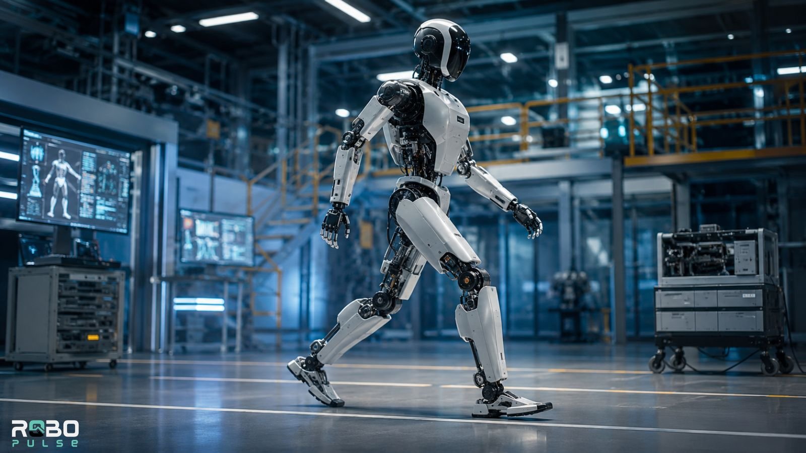
Watch a toddler learn to walk. You’re watching something engineers have chased for six decades.
For a child, walking comes from instinct and repetition. For a robot, every step is a fight against physics. That fight runs on constant, high-frequency calculation.
Bipedal locomotion means moving on two legs. For a humanoid robot, that’s one of the hardest control problems in engineering. It has to stay upright on two narrow feet. It has to do this on uneven ground, around unexpected obstacles, against forces it never planned for.
At the 2015 DARPA Robotics Challenge, this problem broke several teams’ robots in public. Boston Dynamics’ Atlas, among others, toppled the moment a foot met a surface its planner hadn’t modeled — a curb edge, a loose panel. It wasn’t a dramatic mechanical failure. It was a gap of a few milliseconds between what the sensors reported and what the controller could correct for.
That gap is still the whole ballgame in 2026.
This guide breaks down how bipedal locomotion actually works: the physics of balance, the control systems making real-time corrections, and where the field still genuinely struggles.
Why Two Legs Are So Difficult
A four-legged robot has a stable base built in. Three or four feet touch the ground at any moment. It isn’t actively fighting gravity. A wheeled robot is even more stable — it sits flat, always.
A two-legged robot has neither advantage.
During every step, its entire mass balances over one foot. During the swing phase, when one foot is in the air, the robot is technically falling. It doesn’t collapse only because it catches itself with the next step. Over and over. Thousands of times per hour.
Bipedal locomotion isn’t really walking. It’s controlled falling — a continuous cycle of going off-balance on purpose, then recovering before gravity wins.
The margin for error is narrow. A few centimeters off on foot placement. A few milliseconds of delay in a joint correction. An unexpected surface texture. Any one of these can cascade into a fall.
The Gait Cycle: What Happens During Each Step
Every step follows a four-phase sequence called the gait cycle.
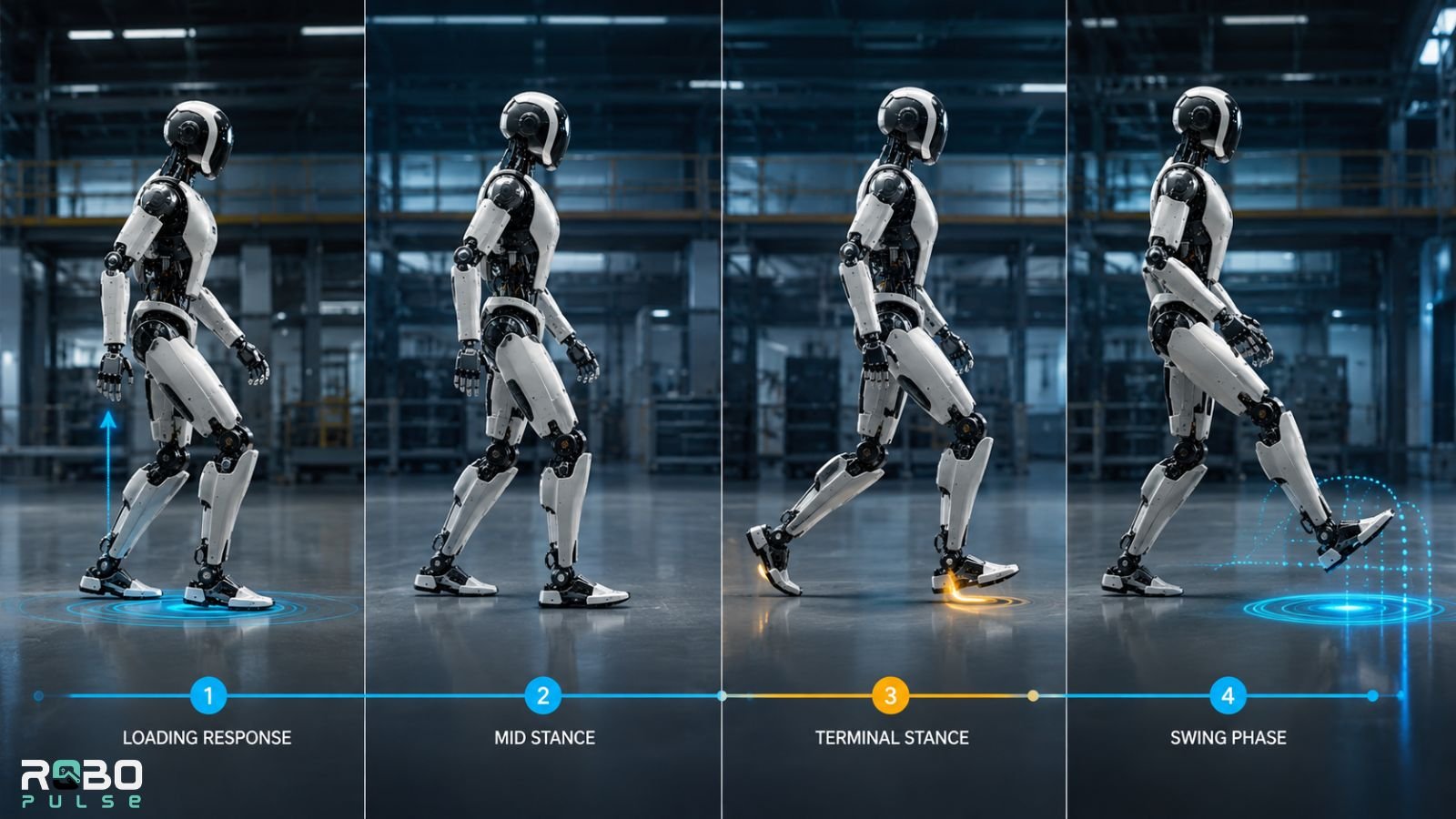
Phase 1 — Loading Response
The foot contacts the ground. Weight transfers forward.
Strain gauges in the ankle register peak forces — often two to three times the robot’s static body weight, compressed into a fraction of a second. At the same moment, IMUs (gyroscopes plus accelerometers) read the body’s orientation and angular velocity. That data joins the force readings at the balance controller. Without it, the system can’t tell a normal heel strike from a stumble.
Phase 2 — Mid Stance
Full body weight sits on one leg. This is the most mechanically demanding moment in the cycle.
Hip abductors work to stop the torso dropping sideways. The knee holds a slight bend — locking it straight would kill shock absorption. The ankle builds tension for push-off. Meanwhile, the opposite leg is already swinging into position. One whole-body controller runs both legs at once: one holding the system up, one repositioning.
Phase 3 — Terminal Stance
The heel rises. Power moves through the ankle. Calf-equivalent actuators fire to generate forward momentum.
This push-off supplies most of the energy in the gait cycle. Get it wrong, and the robot shuffles instead of walking.
Phase 4 — Swing Phase
The foot leaves the ground. A terrain planner, reading depth-camera and LiDAR data, calculates the optimal landing spot mid-flight.
The stance leg, meanwhile, carries the highest sustained loads of the cycle — while running high-frequency torque loops to keep the torso stable.
| Phase | Foot Status | Primary Mechanical Demand |
|---|---|---|
| Loading Response | Foot strikes ground | Impact absorption — 2–3× body weight |
| Mid Stance | Full weight on one leg | Lateral stability — hip abductors at peak load |
| Terminal Stance | Heel rising | Push-off energy generation |
| Swing | Foot in air | Terrain-planned repositioning + stance-leg peak torque |
Modern humanoids complete this full cycle in under a second. Boston Dynamics’ Atlas Electric, built for payload capacity and joint manipulation in commercial deployment, tunes its walking speed for factory-floor reliability over raw sprint speed.
How Do Bipedal Robots Balance? The Zero Moment Point
The Zero Moment Point (ZMP) is the ground location where gravity and inertia combine to produce zero rotational moment. Put simply: it’s the point where the robot is perfectly balanced, right now, this instant.
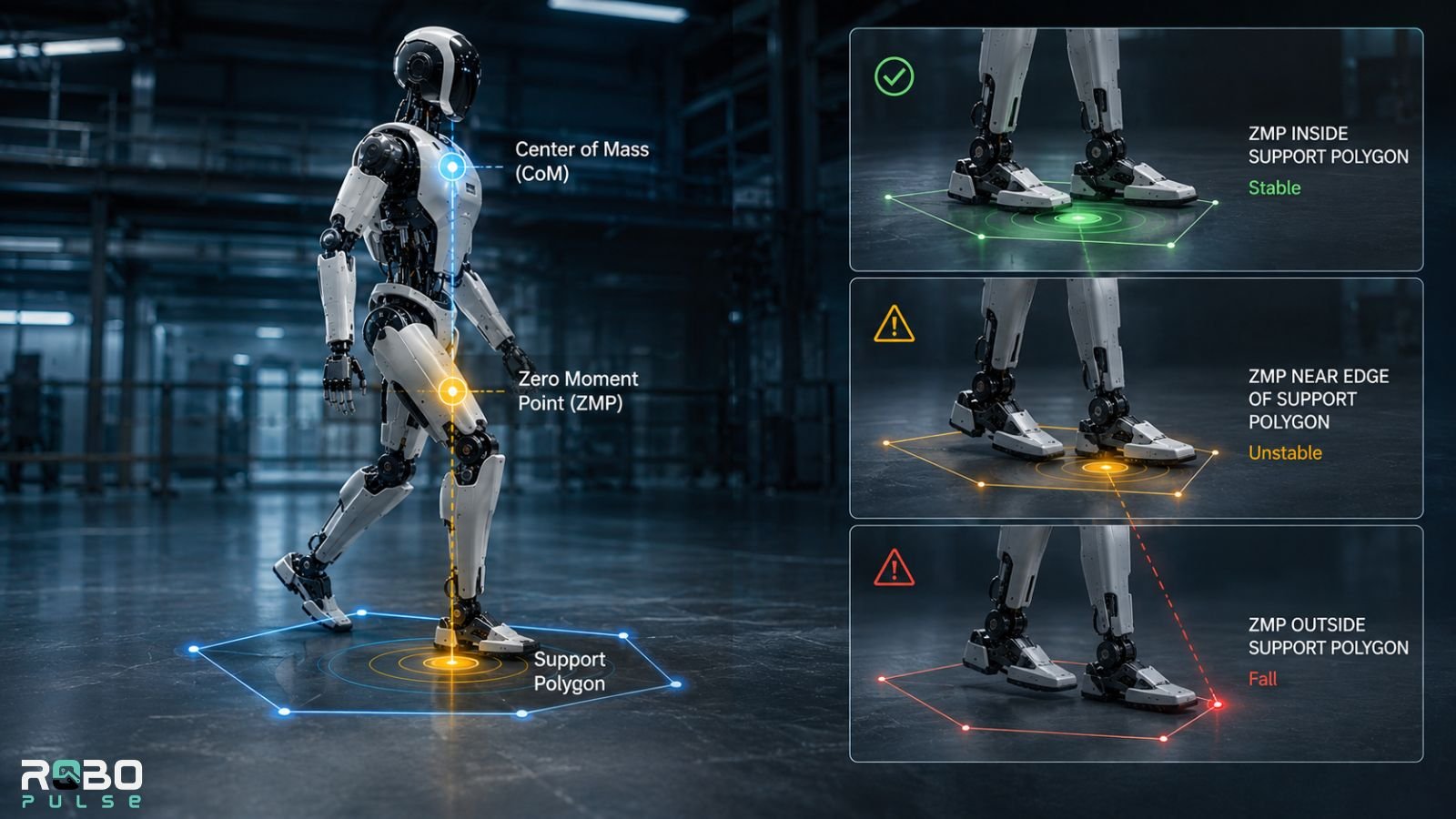
Here’s how the three core concepts connect:
Center of Mass (CoM) ──► moves dynamically in 3D space
        │
        ▼  (gravitational + inertial forces)
Zero Moment Point (ZMP)
        │
        ▼  (must stay bounded within)
Support Polygon (foot/feet contact area) ──► excursion = fall
For the robot to stay upright, the ZMP has to stay inside the support polygon — the ground area covered by the foot or feet. The instant it leaves that polygon, the robot tips.
Think of balancing a broom upright on your palm. As long as the broom’s center of mass stays above your hand, it stays up. Drift past the edge of your palm, and it falls. Your palm is the support polygon. The ZMP is the point that has to stay above it.
This is a simplified model. Advanced controllers — Capture Point, Divergent Component of Motion — intentionally allow brief ZMP excursions during fast walking or recovery. But the underlying principle holds: the further the ZMP strays, the more aggressive the correction has to be.
CoM vs. ZMP, in short
- CoM — the single point where the robot’s mass is effectively concentrated, usually in the torso, shifting with every limb motion.
- ZMP — the ground point where balance forces cancel out, determined by the CoM’s position, velocity, and the forces acting on the robot.
Low-level joint torque loops run near 1,000 Hz. Higher-level MPC planners run at 50–200 Hz. Each layer handles a different timescale of the same balance problem.
How Balance Control Has Evolved
| Era | Dominant Approach |
|---|---|
| 1990s | Static ZMP walking — slow, flat-footed |
| 2000s | Predictive Motion Control — ASIMO era |
| 2010s | MPC + trajectory optimization |
| 2020s | RL + MPC hybrids |
| 2026 | Hybrid learning with adaptive estimators + VLA integration |
The Physics Shortcut: The Linear Inverted Pendulum Model
Simulating a robot’s dozens of joints and 60–80 kg of distributed mass, at full fidelity, in real time, is out of reach on current hardware.
So engineers simplify. The Linear Inverted Pendulum Model (LIPM) treats the robot’s mass as a single point, sitting at constant height, on a massless telescoping leg.
The governing equation, under a constant-height assumption:
x¨=gzcx\ddot{x} = \frac{g}{z_c} x
Here, x is the CoM’s horizontal position, g is gravitational acceleration (9.81 m/s²), and z_c is the constant CoM height above ground.
This tells the controller something simple but critical: the further the CoM drifts from directly above the foot, the faster it accelerates — and the faster the controller has to respond.
It’s an approximation. Knees bend. Torsos pitch. But it’s accurate enough to keep a 60 kg robot walking at human speed, and light enough to run in real time alongside the full sensor stack.
Degrees of Freedom: Six Per Leg Is the Minimum
Each leg needs at least six degrees of freedom (DoF) to execute a full 3D gait cycle.
| Joint | DoF | Function |
|---|---|---|
| Hip | 3 | Flexion/extension, abduction/adduction, rotation |
| Knee | 1 | Flexion/extension only |
| Ankle | 2 | Plantar/dorsiflexion, inversion/eversion |
Fewer than six per leg, and the robot can’t adapt its foot placement to uneven terrain in every direction. More DoF adds adaptability — at the cost of control complexity and actuator count.
Static Balance vs. Dynamic Balance
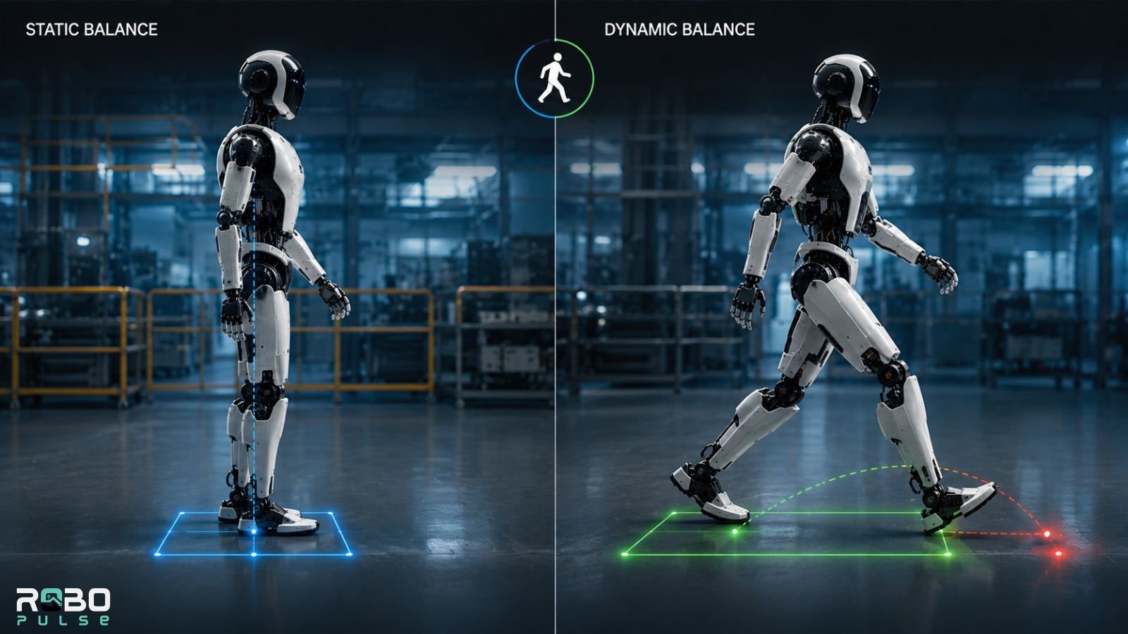
Static balance keeps the ZMP inside the support polygon at every instant. The robot moves slowly, fully planting each foot before lifting the other. Honda’s ASIMO ran this approach through Predicted Motion Control, producing its recognizable flat-footed shuffle: deliberate, cautious, bounded.
Dynamic balance accepts that the robot is momentarily unstable during each step. The ZMP briefly exits the polygon, and the controller plans the next foot placement to catch it before gravity wins. This is closer to how humans actually walk — always slightly falling forward, each step catching us.
Every serious commercial humanoid in 2026 — Unitree G1, Apptronik Apollo, Atlas Electric — runs dynamic balance, layered with adaptive estimators that close the gap between predicted and actual behavior.
| Static Balance | Dynamic Balance | |
|---|---|---|
| ZMP position | Always inside support polygon | Briefly exits during swing |
| Speed | Slow | Human-like |
| Terrain handling | Poor | Strong |
| Push recovery | Weak | Robust |
| Energy efficiency | Low — high static holding torque | Higher — uses momentum |
| Example | Early ASIMO | Atlas Electric, G1, Apollo, Digit |
Passive Dynamics: Letting Physics Do the Work
Modern locomotion doesn’t rely on raw motor power alone. It exploits passive dynamics: a swinging leg, released from active control, arcs forward naturally under gravity — like a pendulum. Engineers shape leg geometry and mass distribution to encourage that arc, cutting the active torque motors need during swing.
This matters for energy. Bipedal robots burn power continuously through their actuators, just to resist gravity while standing still — this is called static holding torque. Every watt saved during swing extends battery life directly.
Purely mechanical passive dynamic walkers — no motors, no computers — demonstrated decades ago that two-legged walking is physically natural, given the right geometry.
The AI Systems Behind Modern Locomotion
Model Predictive Control (MPC)
MPC plans several steps. It calculates the optimal joint-movement sequence over the next 0.5–2 seconds, executes only the first step, then recalculates — continuously.
This lets the robot anticipate balance problems before they happen. If terrain suddenly slopes, MPC catches the deviation and adjusts foot placement before the next step lands, not after. It runs at roughly 50–200 Hz and works best where terrain is fairly predictable.
Reinforcement Learning and the Sim-to-Real Gap
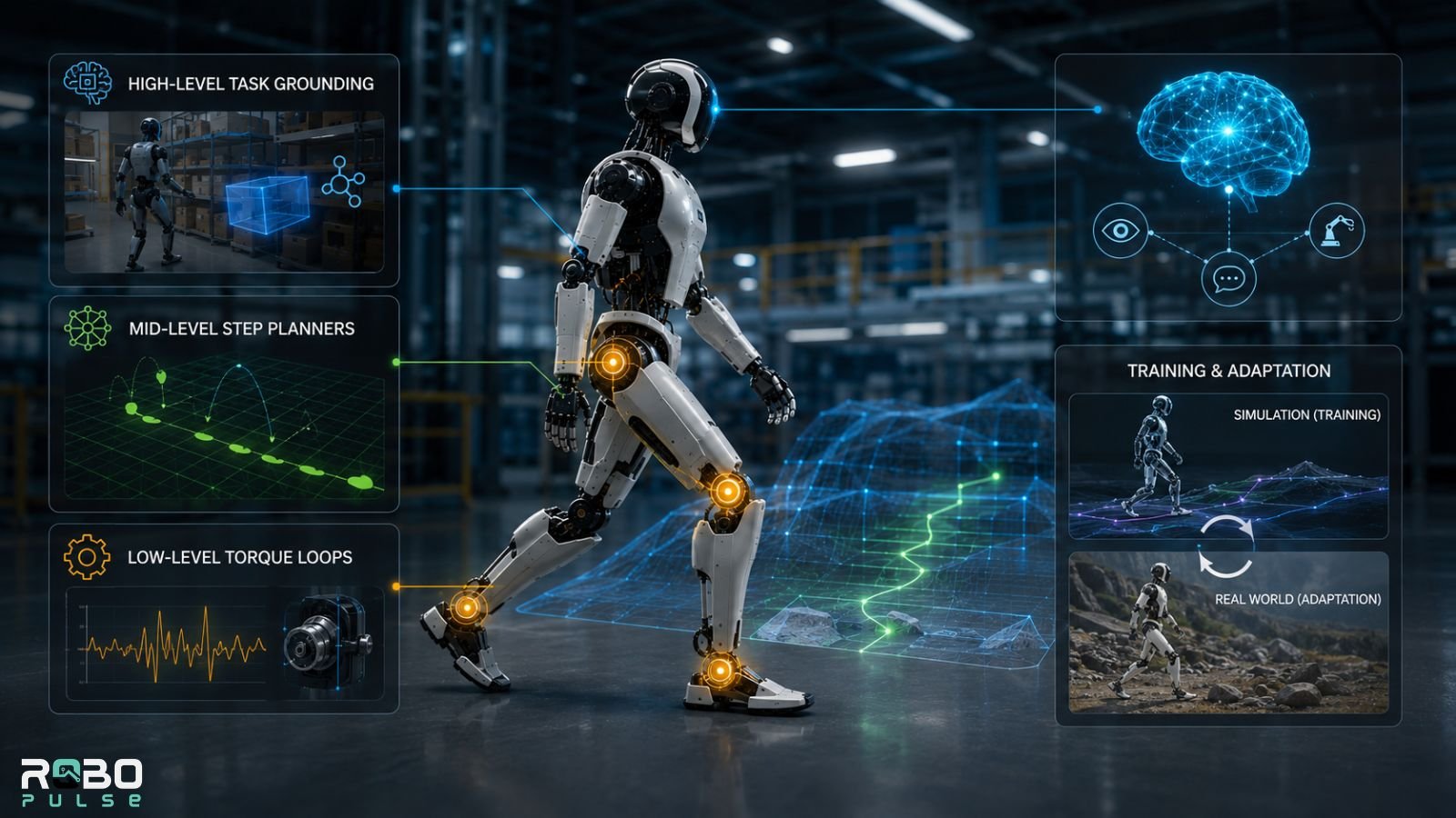
Reinforcement learning (RL) trains a neural network through millions of simulated trial-and-error attempts — often in platforms like NVIDIA Isaac Sim, where a virtual robot can fall and recover far faster than any real-world training allows. The trained policy is then transferred to physical hardware. That step is called sim-to-real.
What actually drives the learning is the reward function — the score the network tries to maximize at every simulated timestep. A typical locomotion reward combines several competing terms:
- + reward for forward velocity — encourages actual progress, not shuffling in place
- − penalty for joint torque volatility — discourages jerky corrections that waste energy and wear actuators
- − penalty for deviation from target CoM height/orientation — keeps the robot upright and close to its expected pose
- − penalty for foot-slip or high-impact landings — pushes toward controlled, low-shock footfalls
- + reward for energy efficiency — pushes the policy to exploit passive dynamics rather than fight them
No single term produces good walking on its own. A policy rewarded purely for forward velocity, for instance, tends to find degenerate gaits that fall forward as fast as possible. The real engineering work is in weighting these terms against each other, so the emergent behavior looks like a stable gait — not an exploit of the reward function.
This is where things get hard. A policy that’s flawless in simulation often fails on real concrete. Joint friction differs from the model by a few percent. Battery voltage sags under load in ways the simulation didn’t capture. Real floors have compliance the rigid virtual ground never had.
These small discrepancies compound. That’s why a sim-trained policy needs adaptive estimators layered on top — real-time systems detecting the gap between expected and actual behavior, correcting on the fly. Agility Robotics went through exactly this with Digit in Amazon fulfillment centers. Not a single transfer — an iterative loop of real-world telemetry feeding back into the simulation, closing the accuracy gap over time.
The Next Shift: From Sim-to-Real Toward Imitation
A newer, arguably more disruptive approach skips physics simulators altogether.
Physical Intelligence’s π (pi) models, including pi-0.7, train locomotion and manipulation policies directly on massive human video and egocentric-motion datasets — not on a simulated physics engine. Instead of asking “what would a simulated robot body do here,” the model asks “what does a human body do in a functionally similar situation,” then adapts that to the robot’s own kinematics.
This sidesteps the sim-to-real gap entirely — there’s no simulation to be unfaithful to reality. It introduces a different gap instead: one between human and robot embodiment, which researchers are still characterizing.
Meanwhile, Vision-Language-Action (VLA) models — like Figure AI’s Helix — ground locomotion decisions in semantic understanding of the environment, rather than pure physics.
The Three-Layer Hybrid Architecture
Most 2026 humanoids now run three layers at once:
| Architecture Layer | Core Frequency | Primary Responsibility | Dominant 2026 Approaches |
|---|---|---|---|
| Low-Level Torque Loops | 1,000 Hz+ | Actuator compliance, impact absorption, slip recovery | Quasi-Direct Drives (QDD), custom electric actuators |
| Mid-Level Step Planners | 50–200 Hz | Trajectory optimization, terrain mapping, predictive balance | MPC, reinforcement learning |
| High-Level Task Grounding | 10–20 Hz | Semantic scene comprehension, zero-shot tool manipulation | VLA models (e.g., Helix), imitation-trained policies (pi-0.7) |
The Hardware That Makes It All Work
Actuators
Actuators aren’t interchangeable across use cases.
Atlas Electric uses high-torque electric actuators developed with Hyundai Mobis, built for industrial payload and joint-range demands. Figure 03 takes a different path — custom actuators built around back-drivability and tactile fingertip feedback sensitive to about 3 grams, letting it distinguish gripping a glass from crushing it. That domestic-safety design focus hasn’t kept the platform out of industrial settings, either — Figure 03 units are also running in industrial logistics pilots. The “domestic vs. industrial” framing is really about design priority, not a hard deployment boundary — a distinction also playing out as companion-oriented humanoids from other manufacturers reach the market.
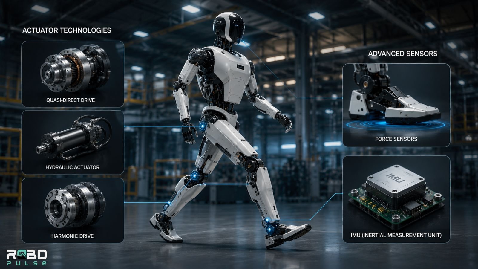
Unitree G1 and Apptronik Apollo both use Quasi-Direct Drive leg joints — low-gear-ratio motors that are highly back-drivable, yielding to unexpected ground contact rather than resisting it rigidly.
Three actuator philosophies dominate current humanoids:
| Actuator Type | How It Works | Strengths | Trade-offs |
|---|---|---|---|
| Quasi-Direct Drive (QDD) | Low gear ratio, motor coupled near-directly to the joint | Highly back-drivable, absorbs shock naturally, good for dynamic balance | Lower peak torque per unit size than geared or hydraulic systems |
| Hydraulic (e.g., older Atlas variants) | Fluid pressure drives pistons at each joint | Very high power-to-weight ratio, strong peak torque | Heavier support systems, harder to make efficient at low load, maintenance-heavy |
| Harmonic Drive | High gear-reduction strain-wave gearing | Precise positioning, compact, zero backlash | Less back-drivable — needs more active compliance control |
The industry’s broader shift from hydraulic to electric actuation over the last decade reflects a bet: back-drivability and efficiency matter more for general-purpose humanoids than raw peak power. Hydraulics still show up where sheer force output is the priority.
Sensors
Strain gauge force sensors, embedded in ankles and feet, measure ground-contact forces in real time — how much force is on each foot, how it’s distributed, whether the foot is starting to slip. Without them, the ZMP calculation is a rough estimate at best.
IMUs function as the robot’s inner ear. They detect orientation, angular velocity, and linear acceleration at rates exceeding 1,000 Hz. When a robot steps on an unexpectedly slippery surface, it’s the IMU that catches the resulting tilt in the first milliseconds — before force sensors have fully registered the slip.
Failure Modes: Why Robots Still Fall
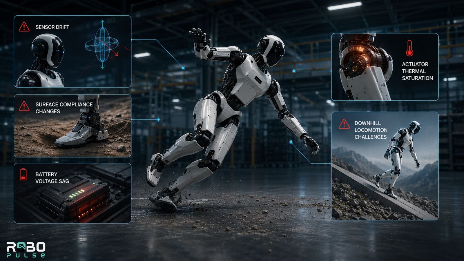
Sensor drift. Small IMU errors compound over extended operation. Without recalibration or sensor fusion, the robot’s model of its own orientation drifts from reality. The standard fix is an Extended Kalman Filter (EKF), or increasingly a factor-graph estimator, fusing IMU readings with leg kinematics, LiDAR, and visual odometry. Each source fails differently, so blending them degrades gracefully instead of diverging when any single sensor gets noisy. Leg kinematics help most here — since the controller already knows every joint angle, it can compute where the foot should be without relying on the IMU at all.
Sudden surface compliance changes. Concrete to a foam mat. A gravel patch. A soft tile. These catch systems off guard when the foot sinks further than the terrain planner predicted.
Battery voltage sag. Under high joint torque, this is a subtler failure mode. As the battery depletes, peak actuator current capacity drops — a corrective torque command can’t be fully delivered. Manageable on flat ground. On stairs, a 10% torque shortfall can be the difference between recovery and a fall.
Actuator thermal saturation. Arguably the least-discussed but most operationally significant failure mode in 2026 deployments. Static holding torque — the continuous effort to resist gravity while merely standing — generates real heat in the motor windings, not just battery drain. Without effective passive dynamics or active cooling, joint controllers throttle output to avoid thermal damage well before the battery is empty. That’s why some humanoids periodically shift stance or briefly “rest” a joint mid-shift, independent of charge level.
Downhill locomotion. Still one of the hardest terrain scenarios. The robot has to actively decelerate its own mass against gravity on every step — the inverse of push-off dynamics — with unusually narrow control margins. Recent 2026 benchmarks, including Georgia Tech’s trials on Cassie and a high-altitude test on Everest-adjacent terrain, still flag downhill walking and cross-legged recovery as primary bottlenecks industry-wide.
Which Robots Do Bipedal Locomotion Best in 2026?
Boston Dynamics Atlas Electric leads on agility and push recovery. Sophisticated MPC, paired with high-torque electric actuation, benchmarks above competitors on dynamic balance.
Agility Robotics Digit leads on real-world deployment reliability. Its RL-trained system, refined through iterative sim-to-real work, handles the unpredictability of live Amazon warehouse floors better than any other shipping commercial humanoid.
Unitree G1 delivers the best locomotion per dollar. At roughly $16,000, it covers terrain that cost ten times as much to handle three years ago.
Apptronik Apollo prioritizes stable, predictable gait tuned for industrial environments — consistent over flashy.
For a closer look at how these platforms stack up spec-for-spec, our robot comparison tool and full robot database break down actuator types, payload, runtime, and pricing side by side.
The Honest Limitations of Current Bipedal Systems
High-speed terrain navigation is still out of reach. Walking slowly over rubble is manageable. Running over it isn’t. The compute demands of high-speed dynamic balance on complex terrain exceed what current onboard processors handle reliably.
Energy remains a hard constraint. Most commercial humanoids run two to four hours before recharging. Static holding torque — and the thermal throttling that comes with it — eats into that continuously, even while just standing still.
Reliable fall recovery is still limited. Most humanoids can’t consistently get up from an unplanned fall unassisted. That constrains deployment anywhere falls are likely.
None of this is permanent. It’s the current frontier — and each hardware and software generation narrows it measurably.
FAQs
Q. How do bipedal robots balance?
Bipedal robots balance by continuously tracking the Zero Moment Point (ZMP), the ground point where gravity and inertia stay in equilibrium. High-speed torque controllers keep the ZMP inside the support area, while Model Predictive Control (MPC) adjusts future footsteps to maintain stability during walking.
Q. What is the biped mechanism of a robot?
A robot’s biped mechanism consists of motor-driven hip, knee, and ankle joints working together to produce human-like walking. Sensors such as IMUs, force sensors, and depth cameras continuously provide data so the control system can maintain balance and adapt each step.
Q. What are the locomotion mechanisms of robots?
The main robot locomotion mechanisms are wheeled, tracked, legged, and hybrid systems. Bipedal locomotion is the most complex because it requires continuous balance control, but it allows humanoid robots to navigate stairs, narrow spaces, and other environments designed for people.
Q. What is reinforcement learning in robot locomotion?
Reinforcement learning trains robot locomotion by allowing a robot to learn through millions of simulated trial-and-error attempts. Instead of following fixed rules, the robot develops walking policies that adapt to different terrain and disturbances.
Q. What is the sim-to-real gap in robotics?
The sim-to-real gap is the difference between how a robot performs in simulation and on real hardware. It occurs because real-world conditions—such as friction, surface compliance, and actuator behavior—never perfectly match the simulation, requiring additional real-world tuning.
Q. How do humanoid robots climb stairs?
Humanoid robots climb stairs using Model Predictive Control (MPC), depth cameras or LiDAR for terrain perception, and precise joint control to place each foot safely. Climbing is reliable on standard stairs, while descending remains more challenging because it requires continuous braking against gravity.
Q. Why do bipedal robots use more power than wheeled robots?
Bipedal robots consume more energy because they must constantly generate joint torque to stay balanced, even while standing still. Wheeled robots only need power for movement, making them significantly more energy-efficient.
Q. Why is bipedal locomotion harder than quadruped locomotion?
Bipedal locomotion is harder because a robot balances on one foot during each step, leaving little room for error. Quadruped robots keep multiple feet on the ground, giving them greater stability and making balance control much simpler.
What Comes Next
The next real frontier is energy efficiency — specifically the thermal side of it, not just battery capacity. Solving efficient, cool-running locomotion at scale unlocks deployment scenarios currently impractical on two to four hours of runtime: extended outdoor inspection, emergency response, agricultural work.
Imitation-learning approaches like pi-0.7, alongside VLA models grounding locomotion in semantic context, represent the most significant architectural shift of the decade. They treat movement not as a pure physics problem, but as something informed by how humans actually move through the world.
Bipedal locomotion is no longer a research curiosity. It’s a commercial reality, improving measurably every quarter — already on display at industry gatherings like Automate 2026, already stocking shelves in Hong Kong convenience stores, and increasingly available through rental fleets in China rather than outright purchase. The question isn’t whether humanoid robots can walk. It’s how well, how efficiently, and where they’ll walk next.
Related: UBTech Launches Hyper-Real Humanoid Robots Built for Companionship